

Preface
Ukraine’s artificial sector has faced unknown challenges in recent times, with frequent grid insecurity and power outages disrupting production for manufactories reliant on 24/7 uptime. For a mid-sized manufacturing factory in central Ukraine — specializing in perfection essence factors for automotive and aerospace customers — indeed, a 30-nanosecond outage could result in $10,000 in losses and missed delivery deadlines.
The plant’s 48V low-voltage ( LV) energy storehouse system was inadequate to handle its 150kW peak cargo, suffering from high energy losses and limited scalability. Hopeless for a dependable, high-power result to decouple from the unstable grid, the customer turned to JBD Energy — a global leader in high-voltage ( HV) battery operation systems( BMS) and artificial energy storage.
This case study explores how JBD’s HV energy storehouse system — integrating rack-mounted LiFePO4 batteries, a personal HV Master BMS, and a mongrel inverter — delivered the adaptability the plant demanded to maintain continued production.
The Solution: Why High Voltage?
High-voltage (400–600V) energy storage is by far more effective than a typical 48V LV system in an industrial setup, such as a factory, in three major ways:
Efficiency: HV systems keep current flow (P = V×I) at a low level, thus they are able to reduce the resistive losses that take place in cables and components. The LV system of this factory was dissipating 12–15% of the energy that was stored during the discharge; with the JBD HV solution, the factory is able to cut down the losses to less than 5%.
Power Handling: High voltage (HV) inverters and batteries are capable of running large loads (100kW+); thus, they can be considered the best solution for heavy machinery (e.g., CNC mills, welding stations) whose main characteristic is the demand for rapid, high-power delivery.
Scalability: HV battery modules come with the feature that they can be connected in series, thereby the factory is able to increase the battery storage capacity from 200kWh to 500kWh or even more as its production expands—without the need for completely changing the system.
“The client’s production line was calling for a solution that would be able to support it, not one that would limit them,” states Ivan Petrov, JBD’s Senior FAE for Eastern Europe. “In order to get the required efficiency, power, and scalability, there was no other option but to go for high voltage.”
System Deep Dive: JBD HV BMS & Battery Array Architecture
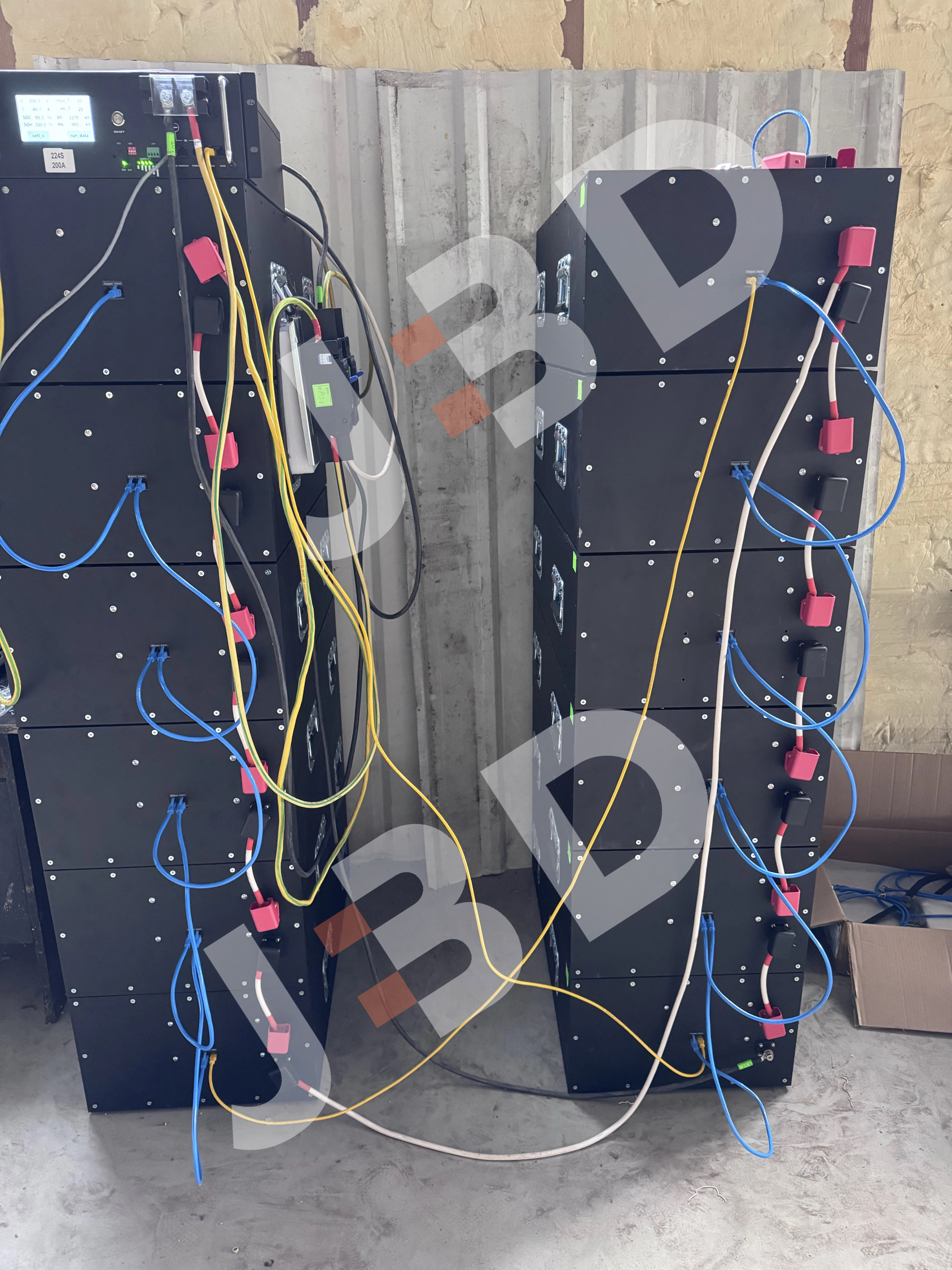
At the core of the setup is a JBD High Voltage Master BMS (Model: JBD-HV-Master-500), which is on top of a 16-module LiFePO4 battery array. The unit BMS is a high-voltage BMS; it controls:
1. Series-Connected Battery Modules
Every single rack-mounted battery module (32V, 12.5kWh) is linked in series to obtain a total system voltage of 512V—perfect for the 100kW factory hybrid inverter. The series connection raises the voltage (very important for high power delivery) while the JBD BMS cell balancing is maintained throughout all 512 cells (16 modules × 32 cells each). This can stop overcharging/overdischarging and prolong battery life by 20–30% more than those without any management.
2. Safety Protocols
High voltage installations necessitate a set of very strict safety regulations, and the JBD BMS is capable of providing such measures:
Insulation Monitoring: Continuous checks for insulation faults (ground faults are the main cause of fire in industrial environments with dust and moisture).
Overvoltage/Overcurrent Protection: The battery array is disconnected immediately if it experiences any overvoltage or overcurrent conditions.
Temperature Control: Works with the HVAC of the factory to not only cool the batteries but also ensure that they are always between 15-35 degrees - this will assure that batteries will complete 6000+ cycles.
3. Communication & Integration
BMS communicates with the inverter, generator, and the grid metering system through the CAN bus. This permits the easy selection of power sources:
Grid Normal: During off-peak hours, the inverter we're using will charge the batteries from the grid, thus also allowing for the injection of excess power to the grid.
Grid Outage: BMS sends a signal within 10ms to power down production from the battery scheduled in the line; a large-scale blackout is not a problem anymore.
Generator Backup: Besides that, in case the batteries no longer hold the charge, the BMS is allowed to do this step itself and start the diesel generator in the factory.
Cabling & Physical Design
The picture discloses the system’s heavy-duty cabling:
Orange Power Cables: These are the wires that carry the high-current DC power between the battery modules (series connection).
Blue Communication Cables: The wires that connect the BMS to each battery module (CAN bus) and the inverter (RS485).
Red Safety Switches: Manual disconnects for the removal of parts, electrically safe and in line with Ukrainian safety standards (DSTU).
The “work-in-progress” look—cables not tied up, temporary labels—gives the installation authenticity: it’s a real situation, not a studio setup. JBD’s field team didn’t beautify the place but made it functional, and thus the system was up and running within 72 hours after they had delivered it and commissioned it.
Integration & Commissioning: Matching the Inverter to the HV System

Image portrays the final phase of integration: the connection of a 100kW hybrid inverter (suitable for 400–600V DC) to the JBD battery bank. To prove this, the JBD team performed thorough on-site testing. The open inverter cover exposes the internal electronic components:
1. Inverter Matching
To establish communication between the BMS and one Deye HV hybrid inverter (model: 100kW HV-1) was chosen by the client. Grid, battery, and generator could be the three power sources utilizing the inverter in the future, as it made this scenario possible. The main points that the JBD team checked were:
Voltage Range: The inverter’s 400–600V DC input matched the battery array’s 512V output.
Power Rating: With 100kW output, the factory peak load of 150kW was mostly met (during normal operation, 50kW was supplied by the grid).
Communication Protocols: The inverter’s CAN bus interface was configured to sync with the JBD BMS, enabling real-time data sharing (state of charge, power flow, fault alerts).
2. Onsite Testing
During the 3 days of the exercise, more than 10 different scenarios of power outage were simulated to check readiness for the following points:
Switching Time: The inverter transitioned from grid to battery power in <10ms—fast enough to prevent machinery from shutting down.
Load Handling: The system supported the factory's 150kW peak load for 2 hours (the longest expected outage).
Safety: The BMS triggered a shutdown when a simulated insulation fault was introduced, protecting workers and equipment.
3. Client Training
JBD’s personnel coached the factory maintenance department on how to operate the BMS’s Internet-based dashboard that could be opened from a PC or a mobile device:
Battery monitoring (cell voltage, temperature).
Charging scheduling (by taking advantage of off-peak grid tariffs).
Minor fault handling (e.g., a loose communication cable).
The manager of the factory’s maintenance commented: "Detail attention was the team's strength, and really they were a class apart. Installing the system was not their only job; they did the teaching too, thus making it easy for us to run it without any failures."
Technical Specifications
| Parameter | Value |
| System Voltage | 512V DC (16 × 32V LiFePO4 modules) |
| Capacity | 200kWh (expandable to 500kWh) |
| Peak Power | 100kW (supports 150kW peak load with grid) |
| BMS Model | JBD-HV-Master-500 (16-module support) |
| Inverter | Deye 100kW HV-1 Hybrid Inverter |
| Cycle Life | 6000 cycles (80% depth of discharge) |
| Efficiency | 95% (AC-DC-AC) |
| Warranty | 5 years |
Conclusion
JBD’s high-voltage energy storage system is more than just a tool for the Ukrainian factory—it is the means of survival. By substituting their old 48V system with a scalable, efficient HV solution, the client has gone:
100% Uptime: There have been no losses of production due to interruptions of the local grid during the 6 months following the installation.
20% Energy Cost Reduction: The device is charged with electricity taken from the grid at off-peak hours, thus lowering energy costs by $1,200/month.
Comfort: The absence of the dreaded downtime, thanks to real-time monitoring and safety features of the JBD BM,S is the client's new state of mind.
This undertaking is a proof of JBD Energy’s pledge to facilitate global energy resilience. No matter if it is a factory in Ukraine, a data center in Southeast Asia, or a microgrid in Africa, our HV BMS and storage solutions are the ones outlasting the toughest conditions on earth.
Do you want to find out how JBD’s HV energy storage system can be of help to your business in combating grid instability? Take a look at our High Voltage BMS product page or get in touch with our team for a project discussion.