

Seamless BMS Inverter Integration is the critical link between battery intelligence and system performance. A mismatch in protocols or capabilities can cripple functionality, limit scalability, and introduce safety risks. JBD's High-Performance BMS is engineered from the ground up for universal compatibility and deep system integration, moving beyond basic monitoring to become the central command unit for your energy storage system.
System Technical Specification: Protocol & Integration
The following table contrasts the limitations of traditional solutions with the advanced, flexible architecture of the JBD High-Performance BMS.
| Feature | Traditional Solution | JBD High-Performance Solution |
| Communication Protocol Support | Often limited to a single, proprietary, or fixed protocol (e.g., only Modbus). | Dual-Port Standardization: Native support for CAN-BUS (250kbit, 29-bit IDs) and Modbus RS485. |
| Protocol Customization | Fixed message structure; difficult or impossible to adapt. | Fully Configurable CAN Protocol. Message IDs, data scaling, and structure are user-definable. |
| System Integration Scope | Basic battery monitoring with limited external interaction. | EMS-Level Integration. Supports black-start functions and full Energy Management System (EMS) dialogue. |
| Environmental Robustness | Standard commercial ratings. | Industrial Endurance: Designed for -40°C to 60°C with IP65 protection and fan cooling. |
| Safety & Redundancy | Basic operational safety within the BMS. | System-Wide Safety Design. Features power redundancy and direct fault state broadcast for immediate shutdown. |
Beyond Basic Communication: The Integration Advantage
True integration means the BMS and inverter operate as a unified system. Our solution’s configurable CAN protocol allows for precise mapping to manufacturer-specific data points, ensuring parameters like State-of-Charge (SOC), charge/discharge limits, and fault flags are interpreted correctly by inverters from Deye, Victron, and other industrial ESS platforms.
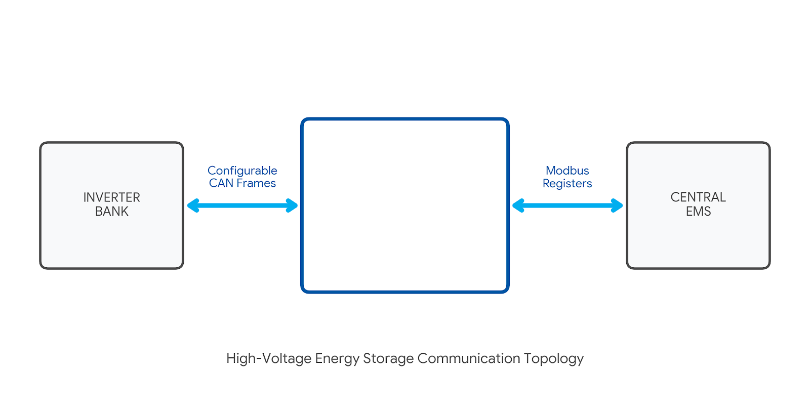
Figure 1: Advanced Communication Topology. The JBD High-Voltage BMS serves as the intelligent hub, offering seamless bidirectional data flow between power inverters and energy management systems through industry-standard protocols and customizable communication logic.
1. Strategic Overview: The Critical Role of BMS Integration
In modern energy storage and microgrid systems, the High-Voltage BMS and the inverter form the critical nexus of intelligence and control.
1.1. The Inverter as the System Brain
The inverter's role has evolved to a central command unit. It makes real-time decisions on solar self-consumption, grid management, and backup—all based on the battery's precise state. Without high-fidelity data exchange, the inverter operates "blind," risking battery damage or suboptimal performance.
1.2. The High Cost of Incompatibility
Incompatibility manifests as:
-
Operational Downtime: Communication faults triggering system shutdowns.
-
Safety Compromises: Inability to preemptively derate power during thermal events.
-
Project Failure: Lengthy custom engineering delays commissioning for 2026/2027 projects.
1.3. JBD's Philosophy: Open Protocol Architecture
JBD eliminates integration fragility by championing an open architecture. Our platforms natively support industry-standard protocols, transforming BMS Inverter Integration into a reliable hardware connection rather than a custom software project.
2. Protocol Landscape: CAN-BUS vs. Modbus RS485

2.1. CAN-BUS Protocol: The High-Speed Nervous System
Controller Area Network (CAN-BUS) excels in real-time environments requiring prioritized messaging.
-
Victron ESS & 250kbit/s: JBD supports the 250 kbit/s standard for Victron systems, broadcasting SOC, SOH, and power limits for millisecond-by-millisecond decisions.
-
Multi-Device Networks: Its multi-master architecture allows multiple battery racks to broadcast on the same bus, ensuring critical alarms never get lost in traffic.
2.2. Modbus RS485: The Industrial Workhorse
Modbus over RS485 is a robust, master-slave architecture ideal for systems where polling intervals (1-2 seconds) are sufficient.
-
Deye Compatibility: Many high-voltage Deye inverters use Modbus RTU. JBD allows precise mapping of internal data (e.g., 300.5V pack voltage) to the specific registers Deye expects, eliminating the common "register mismatch" failure.
Protocol Comparison at a Glance
| Feature | CAN-BUS (e.g., Victron ESS) | Modbus RS485 (e.g., SunSpec) |
| Architecture | Multi-master, peer-to-peer | Master-Slave (polling) |
| Speed | High (250 kbit/s to 1 Mbit+) | Lower (Typ. 9600 to 115200 baud) |
| Typical Use Case | Dynamic, real-time control | Monitoring, legacy integration |
| Wiring | Two-wire (CAN_H, CAN_L) | Four-wire (A, B, GND, V+) |
3. Technical Deep Dive: Major Inverter Platforms
3.1. Deye High-Power Hybrid Inverters
For the SUN-20K-SG01HP3 series, JBD prioritizes data integrity and rapid fault response.
Key Parameter Mapping
| BMS Parameter (JBD) | Deye Register Mapping | Function |
| Pack SOC | Register 0x1000 | Primary input for energy dispatch. |
| Total Voltage | Register 0x1001 | System validation and shutdown thresholds. |
| Current Limit | Register 0x1002 | Power limiting and Coulomb counting. |
| Charge Enable | Register 0x1010, Bit 0 | Immediate command to cease charging. |
3.2. Victron ESS Ecosystem
Integration with Victron leverages a plug-and-play experience via the native CAN-BMS protocol.
-
System Autoconfiguration: Upon connection, the BMS broadcasts capacity and chemistry. The Victron Cerbo GX automatically configures the UI.
-
VE.Bus Control: Allows the BMS to initiate dynamic current limiting or coordinated system shutdowns directly through the GX device.
4. Configuration and Commissioning Workflow
4.1. Pre-Installation Checklist
-
Firmware: Ensure BMS is loaded with the latest 2026 certified firmware.
-
Tools: High-voltage isolation tester (1000V DC) and JBD PC Suite v4.2+.
-
Documentation: CAN FD message sets and inverter interface guide.
4.2. Step-by-Step Protocol Configuration
-
Connection: Connect to the BMS master via USB-CAN dongle.
-
Initialization: Set battery chemistry (LFP/NMC), series count, and nominal Ah.
-
Mapping: In the "CAN Mapping" tab, select the inverter profile (e.g., SunSpec 702 or SMA).
-
Calibration: Verify cell voltage accuracy to within ±2mV.
Frequently Asked Questions (FAQ)
-
Q: Is JBD truly plug-and-play with Victron MultiPlus-II?
-
Yes. It uses the required 250kbit/s, 29-bit identifier protocol for instant recognition.
-
-
Q: Can I use both ports at once?
-
Yes. You can use Port 1 (CAN) for the inverter and Port 2 (RS485) for an external EMS or SCADA system simultaneously.
-
-
Q: What happens during a fault?
-
The BMS broadcasts a high-priority "Disable" flag. The inverter is programmed to interpret this and cease power conversion in $<100$ms.
-
Ready to Scale?
Stop compromising on compatibility. Deploy the JBD BMS for deterministic safety and seamless multi-vendor interoperability.
[Download Technical Datasheet] | [Book a Topology Consultation]