

Strategic Overview
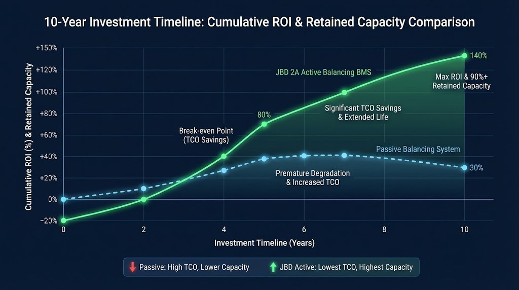
For CTOs and project finance managers, the primary metric for a High-Voltage Energy Storage System (HV ESS) is total lifetime return. Achieving this requires a fundamental shift in perspective: operational longevity and reliability are not just engineering goals but the core drivers of ROI. Traditional Battery Management Systems (BMS) with passive balancing fail to address the primary degradation mechanism in large-format LiFePO4 systems—chronic state-of-charge (SOC) divergence. Implementing a 2A **Active Balancing BMS** is therefore not an incremental upgrade, but a foundational technology for long-term asset preservation and financial performance.
The Large-Cell Reliability Crisis
The industry-wide shift to 280Ah+ cells introduces a critical, often underestimated, financial risk: voltage divergence. While a 0.1V differential may seem minor, it represents a massive energy imbalance at this scale. For a 280Ah cell, a 0.1V difference equates to approximately 90kJ of mismatched energy within the pack. This chronic imbalance forces the system to operate within a reduced voltage window, locking away usable capacity. If this leads to just 10% of the installed pack capacity being perpetually unavailable, the effective capital cost per usable kWh rises proportionally, directly eroding the project's financial foundation.
Total Cost of Ownership of Imbalance
The financial impact of imbalance extends beyond lost capacity. Systems relying on passive balancing convert excess energy into heat, which must be managed. This increases HVAC and cooling operational expenditures (OPEX) and can necessitate the de-rating of other system components to manage thermal loads, compromising overall system output. In contrast, a 2A **Active Balancing BMS** transfers energy between cells with high efficiency, maintaining a minimal thermal footprint. This reduces ancillary OPEX and preserves the system's designed performance, contributing to a lower TCO.
Future-Proofing Through Scalability
Investment decisions must account for technological evolution. The efficacy of a passive balancer diminishes as cell capacity and pack size increase. A 2A active balancer’s capability, however, scales directly with these parameters. It is uniquely equipped to manage the energy imbalances in today's 280Ah cells and the next generation of even larger formats, protecting your capital investment against future cell technology advancements and ensuring system performance remains optimal throughout its lifecycle. This makes the active balancing BMS a critical, future-proof component for any strategic energy storage asset.
The Physics of Failure: Why Passive Balancing Fails Large-Format Cells
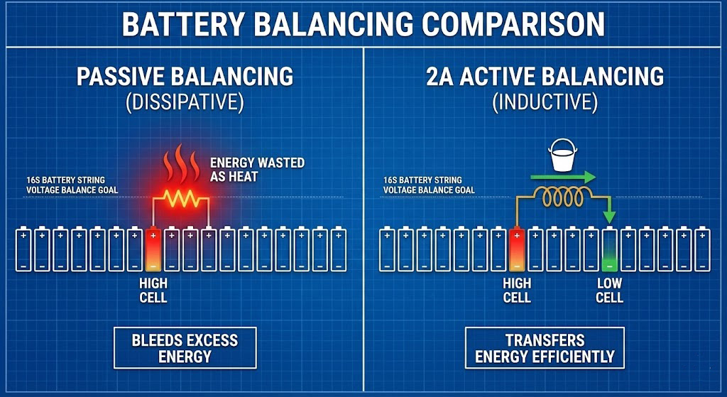
For large-format energy storage systems (ESS), the choice of a battery management system (BMS) balancing strategy is not merely an engineering preference—it is a thermodynamic imperative. Passive balancing, which dissipates excess energy as heat, is fundamentally inadequate for high-capacity, long-duration applications. Its failure is rooted in the laws of physics, creating a cycle of inefficiency and accelerated degradation that no component quality can overcome.
The Energy Transfer Equation: A Battle of Time and Waste
The core function of balancing is to transfer excess charge from a higher-voltage cell to the pack average. The governing equation is simple: **Energy = Current × Voltage × Time**.
Consider a common scenario in a modern 280Ah lithium iron phosphate (LiFePO4) ESS: a single cell develops a 10 Amp-hour (Ah) excess charge imbalance.
* **With a typical 500mA passive balancer**, this energy is burned off as heat across a resistor. The required time is:
* **Time = Energy / (Current × Voltage)** ≈ 10 Ah / (0.5 A) = **20 hours** of continuous operation.
* During this entire period, the system wastes ~16.8W of power (0.5A × 3.4V) per balancing channel, directly converting valuable stored energy into heat.
* **With a 2A active balancing BMS**, energy is redistributed via inductors or capacitors with >90% efficiency. The same correction takes:
* **Time** ≈ 10 Ah / (2 A) = **5 hours**.
* The vast majority of the transferred energy is conserved within the battery pack, enhancing overall system efficiency and runtime.
This stark contrast highlights that passive balancing is not just slower; it is energetically lossy by design, making it unsuitable for systems where total cost of ownership (TCO) and energy throughput are critical.
Thermal Runaway of Performance
The heat generated by passive balancing resistors does not simply vanish. It raises the local temperature of the target "high" cell. Elevated temperature accelerates key degradation mechanisms within lithium-ion cells, including solid electrolyte interphase (SEI) layer growth and electrolyte decomposition.
This creates a vicious, self-reinforcing cycle:
1. A cell becomes slightly imbalanced.
2. The passive balancer activates, heating the cell.
3. The localized heat accelerates that specific cell's degradation rate.
4. The degraded cell's impedance and self-discharge characteristics diverge further from its neighbors, **increasing the imbalance**.
5. The balancer must now work longer and hotter to correct a larger discrepancy, further accelerating degradation.
This "thermal runaway of performance" ensures that the very mechanism intended to maintain pack health actively undermines it, leading to premature capacity fade and reduced system lifespan.
The Critical Relevance of C-Rate
The effectiveness of a balancing current must be evaluated relative to the cell's capacity, expressed as a C-rate. For large-format cells, this exposes the futility of low-current passive systems.
* For a 280Ah cell:
* A 2A balancing current represents a **~0.007C** rate.
* A 0.5A balancing current represents a **~0.002C** rate.
A meaningful corrective force must exceed the natural divergence forces within the pack, such as differential self-discharge rates and minor variations in coulombic efficiency. In many large-format ESS packs, the inherent divergence rate can exceed 0.002C. A 0.5A passive balancer is therefore often fighting a losing battle, unable to keep up with the natural tendency of cells to drift apart. In contrast, a 0.007C rate provided by a robust **Active Balancing BMS** delivers a decisive corrective force, ensuring pack convergence and long-term stability.
Conclusion: Passive balancing is thermodynamically lossy, thermally detrimental, and often underpowered for the scale of modern ESS. Moving to an **Active Balancing BMS** is not an incremental upgrade but a necessary shift to a physics-compatible solution that ensures efficiency, longevity, and reliable performance.
Technical Deep Dive (Micro)
This section details the architecture and operational logic of JBD's high-performance **Active Balancing BMS**, designed for robustness and scalability in large-scale High-Voltage Energy Storage Systems (HV ESS).
Topology Analysis: Bidirectional DC-DC Energy Shuttling
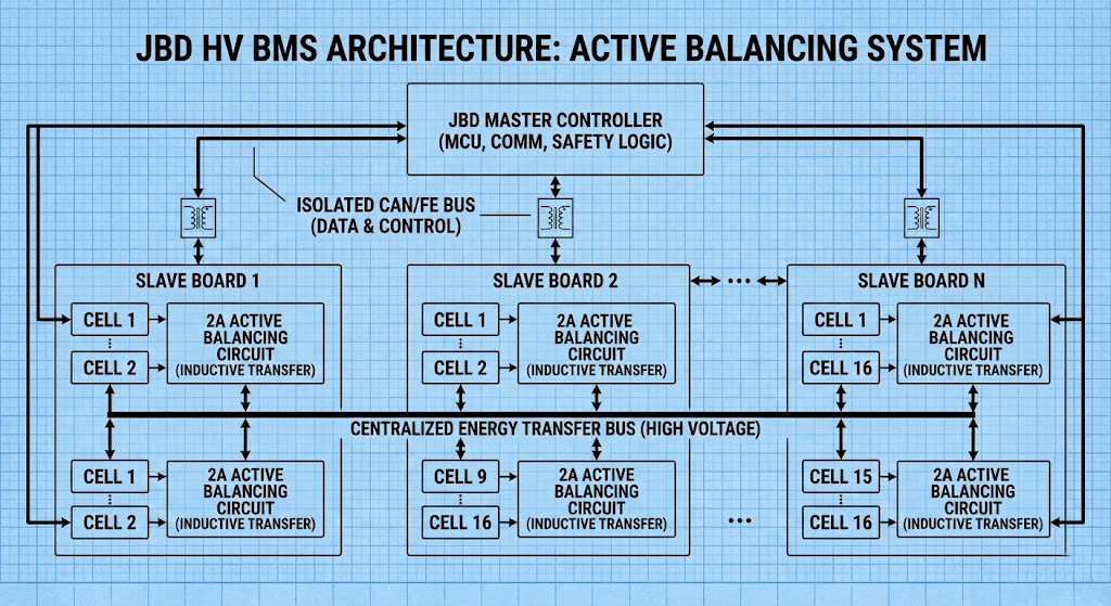
JBD's 2A active balancing solution employs a centralized, inductor-based bidirectional DC-DC converter topology. Unlike passive balancing, which dissipates excess energy as heat, this topology actively shuttles energy from cells with higher state-of-charge (SOC) to those with lower SOC.
The core switching mechanism utilizes a multi-phase flyback or buck-boost architecture per slave board, connected to a centralized energy transfer bus. When the control algorithm identifies a target cell pair, MOSFETs are switched to create a current path through the inductor. Energy is first drawn from the higher-voltage cell and stored in the inductor's magnetic field. The switches then reconfigure to discharge this stored energy into the lower-voltage cell. This "shuttling" action, operating at a nominal 2A, achieves superior energy transfer efficiency (>85%) compared to passive methods, directly improving system runtime and reducing thermal load.
Precision Sensing Foundation
The efficacy of any active balancing algorithm is fundamentally constrained by measurement accuracy. JBD's system is built upon a high-precision voltage-sensing foundation, with cell voltage measurement accuracy of ±2mV. This granular data is critical for the algorithm to correctly identify the cell with the highest and lowest potential, ensuring energy is transferred where it is most needed. Inaccurate sensing would lead to inefficient balancing or, worse, incorrect energy transfer that could exacerbate cell divergence.
Protocols for Scalability: Isolated CAN/FE Communication
To maintain signal integrity and operational safety in high-cell-count configurations (e.g., 60S+), the architecture utilizes isolated communication channels between the master controller and slave boards. Isolated CAN (Controller Area Network) or FE (Functional Earth) protocols are implemented. This isolation prevents ground potential shifts in long battery strings from corrupting data or damaging controllers, ensuring reliable command and data transmission for the **Active Balancing BMS** across the entire high-voltage stack.
Algorithm Logic & Current Management
The balancing trigger employs a hybrid voltage-and-SOC-based model. The primary trigger is a cell voltage deviation exceeding a set threshold (e.g., >10mV). For more sophisticated management, this is correlated with SOC calculated via coulomb counting and model-based estimation. Once triggered, the algorithm identifies the single highest-voltage cell as the source and the single lowest-voltage cell as the target. The 2A balancing current is typically applied in a pulsed manner, with duty cycles managed by the master controller. This pulsed operation allows for continuous monitoring of cell voltage and temperature. The current is automatically derated or paused based on real-time slave board and cell temperature feedback, ensuring safety and longevity. The process is continuous and automatic, working in the background to maintain pack homogeneity with minimal host processor intervention.
| Technical Parameter | Standard Passive Solution | JBD Advanced Active Solution | Engineering Value & Impact |
| Peak Balancing Current | 100mA - 500mA | 2.0A (Continuous) | 4x to 20x faster correction of SOC drift in 280Ah+ cells. |
| Energy Transfer Efficiency | 0% (Dissipative) | >90% (Inductive Transfer) | Drastically reduces thermal stress and recovers >90% of unbalanced energy. |
| Operational Logic | Top-of-Charge only | Static, Charge, & Discharge | Provides full-lifecycle maintenance, preventing premature under-voltage cutoffs. |
| Voltage Sensing Accuracy | ±5mV to ±10mV | ±2mV (High-Precision ADC) | Minimizes false balancing triggers and provides a stable foundation for SOC algorithms. |
| Localized Heat Generation | Significant (Resistor-based) | Negligible (Inductive Topology) | Preserves electrolyte health and prevents localized "Hot Spots" in the pack. |
| Communication Interface | Basic UART / I2C | Isolated CAN / RS485 | Industrial-grade noise immunity for high-voltage (1000V+) stack configurations. |
| System Scalability | Fixed (Typically 16S) | Modular Master-Slave | Seamlessly scales from C&I projects to multi-megawatt utility-scale ESS. |
Section 4: Quantitative Comparison & System Integration Guidelines
Implementing a high-performance **Active Balancing BMS** moves from theory to practice through rigorous specification benchmarking and meticulous system integration. For project engineers and installation technicians, understanding these concrete metrics and physical integration points is critical to realizing the full benefits of a 2A balancing system, such as minimized cell voltage spread and maximized available pack capacity.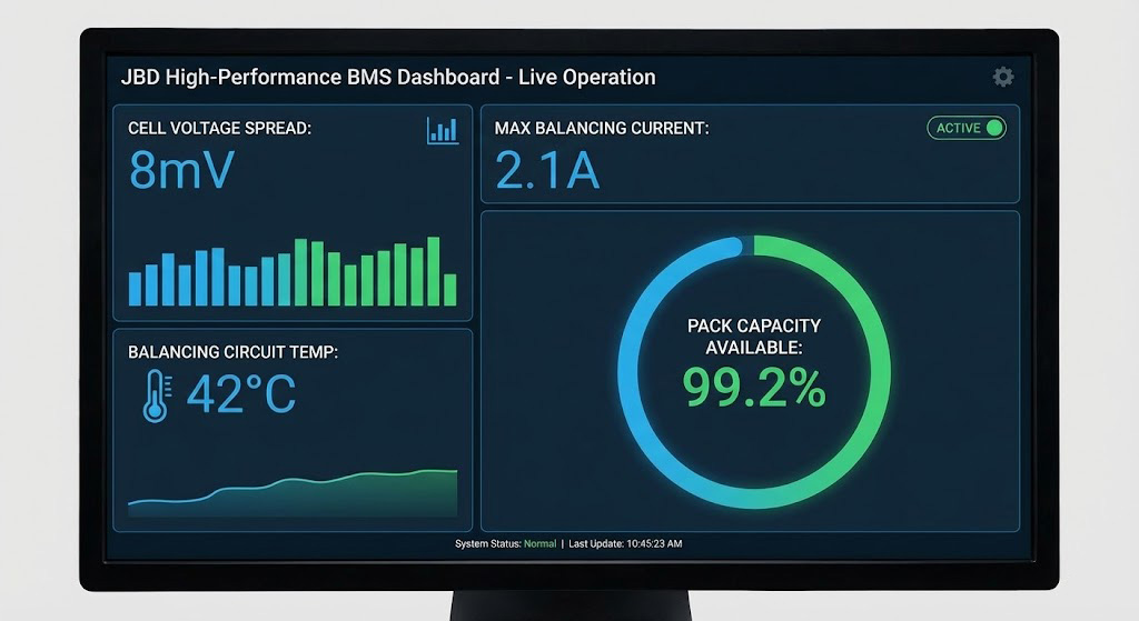 Figure 4: Real-time operational data from a JBD Active Balancing BMS, demonstrating a tight 8mV cell voltage spread and optimized energy availability.
Figure 4: Real-time operational data from a JBD Active Balancing BMS, demonstrating a tight 8mV cell voltage spread and optimized energy availability.Specification Benchmarking
The theoretical performance of an **Active Balancing BMS** is defined by its electrical and operational specifications. The following table provides the key quantitative benchmarks that must be verified against your system requirements.
| Parameter | Fine-Tuned Specification | Engineering Significance & Competitive Edge |
| Balancing Current | 2.0A Continuous (Per Channel) | Dynamic SOC Recovery: Directly addresses the "Time Constant" bottleneck. Corrects a 2.8Ah (1%) imbalance in a 280Ah cell in <1.5h, preventing uncorrected drift during standard C/2 or C/4 cycles. |
| Isolation Voltage | 1500V DC / 2500V AC (1 min) | Dielectric Integrity: Complies with IEC 62109-1 standards. Provides galvanic isolation to prevent ground loop interference and ensure chassis safety in 1000V+ utility-scale battery stacks. |
| Comm. Interface | Dual-Channel Isolated CAN 2.0B / CAN FD | System Interoperability: Supports standard J1939 or custom CAN protocols. The isolation layer prevents HV transients from damaging the Master MCU or external SCADA/Inverter hardware. |
| Comm. Rate | 250kbps - 1Mbps (Programmable) | Data Determinism: High bandwidth ensures real-time telemetry (all cell voltages and temps) is updated within <50ms, critical for fast-acting protection logic and inverter synchronization. |
| Operating Temp. | -40°C to +85°C (Automotive Grade) | Extreme Environment Resilience: Utilizing AEC-Q100 qualified components. Ensures logic stability in outdoor ESS containers subject to extreme diurnal temperature swings without thermal derating. |
| Voltage Accuracy | ±2mV (Typ.) / ±5mV (Full Temp Range) | Precision Foundation: Critical for Coulomb Counting and OCV-based SOC estimation. High accuracy prevents "ghost balancing" caused by sensor noise, preserving cell energy and cycle life. |
| Balancing Topology | Isolated Inductive Flyback | Non-Adjacent Transfer: Unlike switched-capacitor types, JBD can transfer energy between any two cells in the string, maximizing balancing window efficiency and minimizing energy hops. |
| Sensing Resolution | 14-bit to 16-bit ADC | Granular Monitoring: Enables the detection of micro-shorts and subtle internal resistance (IR) rise, allowing for predictive State-of-Health (SOH) diagnostics. |
Installation & Wiring Considerations
Proper physical integration is non-negotiable for measurement accuracy and system reliability.
1. **Current-Sense Shunt Installation:** The shunt must be installed in the **negative pack lead** with Kelvin (4-wire) connections. Ensure the sense wires are twisted-pair and routed away from high-current cables or switching nodes to avoid noise injection into the critical current measurement.
2. **Voltage Sense Harnesses:** Maintain balanced harness lengths from the BMS board to each cell tap point. Mismatched lead lengths can introduce parasitic resistance, leading to apparent voltage measurement errors that can falsely trigger or inhibit balancing.
3. **Communication Bus Termination:** The CAN bus (CAN_H, CAN_L) must be terminated with a 120Ω resistor at each physical end of the network. A single missing or incorrect termination will cause communication errors and BMS dropout.
Software Configuration
Post-installation, these software parameters must be configured to align the BMS protection and balancing logic with your specific battery chemistry and operational profile. * **Balancing Trigger Threshold:** This is the voltage delta between the highest and lowest cell that must be exceeded before the **Active Balancing BMS** engages. Setting this too low may cause unnecessary balancing; setting it too high allows imbalances to grow. * **Balancing Temperature Window:** Define the minimum and maximum cell temperatures at which balancing is permitted. Balancing is typically disabled at low temperatures (e.g., <5°C) due to reduced cell efficiency and at very high temperatures (e.g., >50°C) to manage thermal load. * **Balancing Aggressiveness Profile:** This setting controls the behavior of the 2A balancing current. A "Continuous" profile applies the full current whenever enabled, ideal for fast correction during maintenance. A "Pulsed" or "Thermal-Limited" profile modulates the current to manage heat dissipation in the balancing circuitry during normal operation.
The Future-Proof Choice: From Compliance to Competitive Advantage
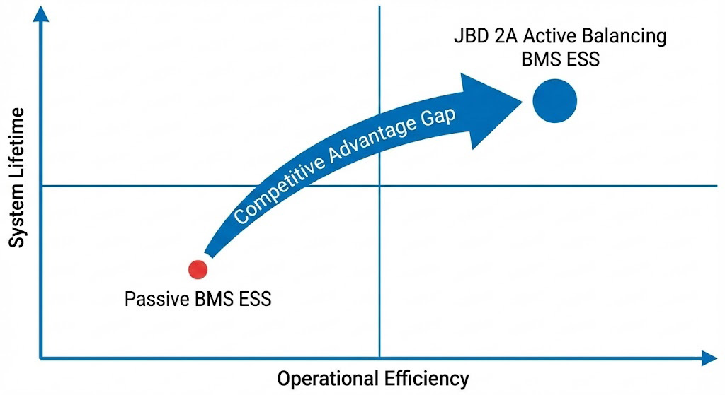
For executives and product strategists, the decision to specify a Battery Management System (BMS) transcends basic safety compliance. It is a strategic investment in the asset's core performance and longevity. Adopting an advanced **Active Balancing BMS** transitions an energy storage system (ESS) from a commodity component to a durable, high-performance asset that delivers superior lifetime value and aligns with the industry's trajectory toward intelligent, sustainable design.
Aligning with the Industry Trajectory
The industry is rapidly evolving beyond passive monitoring toward predictive health management, as evidenced by the growing focus on "A.I. based BMS" and "active balancing." JBD's 2A active balancing solution provides the essential hardware foundation for this future. Maintaining exceptional cell voltage uniformity (<20mV spread), it creates a stable, consistent data environment. This high-fidelity operational state is a prerequisite for deploying effective predictive analytics and AI-driven algorithms for lifespan forecasting and preventative maintenance, ensuring your infrastructure is ready for next-generation energy management.
Warranty & Insurance Implications
A system with demonstrably superior cell consistency represents a lower long-term risk profile. The proven reduction in accelerated cell degradation and thermal stress directly impacts the total cost of ownership (TCO) and can influence critical commercial terms. Insurers and warranty providers increasingly recognize that advanced BMS technology mitigates the primary failure mechanisms in lithium-ion packs. Specifying a high-performance **Active Balancing BMS** can therefore be a decisive factor in securing more favorable warranty conditions and potentially reducing insurance premiums over the system's 10-15 year lifespan.
The Essential Requirement for Long-Duration ESS
For any long-duration ESS project where reliability and TCO are critical, this is the conclusive argument: specifying a BMS with high-current active balancing is no longer an optional upgrade—it is a non-negotiable technical decision for safeguarding your capital investment and ensuring projected financial returns.
Conclusion: The Indispensable Role of the 2A Active Balancing BMS
For all stakeholders involved in HV ESS projects, the evidence is clear. Where reliability and total cost of ownership over a 10-15 year lifespan are paramount, the specification of a BMS with high-current active balancing is a fundamental technical imperative. It is the single most effective electronic measure to mitigate the primary degradation mechanism in lithium-ion battery packs—cell imbalance. By ensuring uniform cell health, the JBD 2A **Active Balancing BMS** transforms the ESS from a depreciating component into a durable, high-performance asset, securing its value and performance for the long term.
Frequently Asked Questions (FAQ)
**Q: How does 2A active balancing extend battery life compared to passive balancing?** Passive balancing accelerates degradation by dissipating excess energy as heat, creating localized hot spots, and failing to correct State-of-Charge (SOC) drift in large-format cells. In contrast, active balancing maintains tight cell voltage uniformity (typically <20mV spread) by intelligently redistributing energy between cells. This minimizes stress on individual cells, reducing the rate of capacity fade. Empirical data from cycled packs demonstrates this approach can extend overall cycle life by **>20%** compared to passively balanced systems. **Q: Is 2A balancing current necessary for all applications, or is it overkill for smaller packs?** The necessity scales with cell capacity and total string energy. For large-format ESS cells (e.g., 200Ah+), a 2A balancing current provides a meaningful corrective rate of approximately **0.01C to 0.005C**, enabling effective management during charge/discharge cycles. For smaller packs, the same robust hardware operates at significantly lower relative stress, offering substantial design headroom, faster balancing convergence, and future-proof scalability. This makes it a universally robust and reliable choice across applications. **Q: What is the typical efficiency of JBD's active balancing circuit, and how does that impact system runtime?** JBD's inductive active balancing topology operates at **>90% efficiency**. Unlike passive balancing, which wastes 100% of the bled energy as heat, over 90% of the transferred energy is preserved within the battery pack. For illustration, a system continuously balancing 100W would save >90W of energy that would otherwise be lost. This directly increases available system runtime, reduces the thermal load on the enclosure, and lowers cooling energy requirements, contributing to higher overall system efficiency. **Q: How does the BMS ensure safety during high-current active balancing?** Safety is ensured through a multi-layered protection strategy.
**1) Algorithmic Controls:** Balancing is automatically suspended if any cell voltage moves outside predefined safe limits or if temperature exceeds configured thresholds (e.g., >45°C).
**2) Circuit Protection:** Each balancing channel incorporates independent fusing and is designed with safe temperature derating to handle the 2A current continuously.
**3) System-Level Compliance:** The JBD HV BMS is engineered to meet the rigorous requirements of IEC 62619 safety standards, ensuring reliable operation in large-scale energy storage, which govern critical requirements like isolation, creepage, and clearance for high-voltage systems. **Q: Can this BMS integrate with existing energy management systems (EMS) or solar inverters?** Yes. The JBD HV BMS is designed for seamless integration, typically featuring standard industrial communication interfaces such as **CAN 2.0B and RS485**. These interfaces broadcast comprehensive, real-time data packs—including individual cell voltages, temperatures, state-of-charge (SOC), state-of-health (SOH), and alarm statuses—using open or documented protocols (e.g., JC-BMS CAN). This allows for direct and straightforward integration with most commercial Energy Management Systems (EMS), SCADA platforms, and hybrid inverter systems for centralized monitoring, control, and data logging.