

Scaling battery systems beyond 400V presents formidable engineering and economic challenges. Traditional centralized Battery Management Systems (BMS) often buckle under the complexity, cost, and electromagnetic noise inherent in high-voltage applications. The JBD HVBMS-V1, built on a robust Master-Slave BMS architecture, is engineered to overcome these barriers, providing a scalable, reliable, and cost-effective solution for utility-scale energy storage.
**[Technical Table Extracted]**
| Feature Category | Traditional Centralized BMS | JBD HVBMS-V1 (Master-Slave) Solution | Technical Advantage |
| Scalability & Voltage | Fixed 12s–48s configuration; cascading requires complex hardware redesign. | Modular Expansion: Supports up to 15-32 Slaves (BCUs) in series, reaching 1000V+. | Future-proof for High-Voltage ESS and EV charging. |
| Wiring & Topology | Point-to-Point: Massive wiring harness; every cell wire must return to the central hub. | Daisy-Chain Topology: Minimalist 2-wire loop between modules using shielded twisted pairs. | Reduces harness weight by ~70% and lowers fire risk from wire abrasion. |
| Signal Integrity | Vulnerable to EMI/EMC noise over long analog sensing wires; signal attenuation. | Digital Galvanic Isolation: RS-485/isoSPI daisy-chain (EN 61558); noise-immune digital bus. | Ensures rock-solid data transmission in high-frequency inverter environments. |
| Sensing Precision | V: ±5mV; I: ±1% FS. Standard industry-grade shunt sensing. | Ultra-Precision Grade: V: <±2mV; I: <±0.5% FS; T: ±1°C. | Improves SOC/SOH estimation accuracy, extending battery life by 10-15%. |
| Balancing Strategy | Limited passive balancing (<50mA) due to thermal density in a single board. | Distributed Balancing: Each Slave handles localized balancing (100mA–200mA+ per cell). | Effectively manages large-capacity cells (280Ah/300Ah+) with high consistency. |
| Safety & Redundancy | Single Point of Failure: If the main board fails, the entire battery pack is offline. | Partitioned Architecture: Independent Slave monitoring; if one slave fails, the system can bypass or isolate safely. | Aligns with ISO 26262 (ASIL-C/D) and IEC 61508 functional safety workflows. |
| Integration & Comm. | Basic CAN/RS485; often lacks cloud/IoT native support. | Rich Ecosystem: 3×CAN, 1×RS485, 1×RS232; integrated Bluetooth/4G/WiFi cloud monitoring. | Seamlessly communicates with Tier-1 inverters (Growatt, Deye, Victron, etc.). |
| Maintenance (O&M) | High MTTR (Mean Time To Repair); requires a complete teardown to fix sensing faults. | Plug-and-Play Maintenance: Faulty Slaves can be hot-swapped or replaced individually. | Drastically reduces downtime and field service costs for commercial sites. |
1. Strategic Overview (Macro): The Case for Master-Slave BMS in Utility-Scale Storage
For CTOs and System Integrators, the transition to a Master-Slave BMS is a strategic decision with direct bottom-line impact. The core value proposition addresses the critical pain points of scaling: conquering electromagnetic interference (EMI) that corrupts data, eliminating the wiring harness complexity that drives up installation cost, and enabling true modularity for flexible capacity expansion.
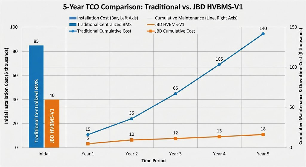
The ROI and TCO analysis are compelling. The simplified daisy-chain topology slashes installation labor and material costs compared to a star-wired, centralized system. Maintenance costs are fundamentally lowered through modularity; a faulty slave unit can be swapped in minutes without taking the entire system offline, minimizing downtime. Furthermore, the superior monitoring accuracy (<±2mV) and balancing control extend cell lifespan, protecting the core asset and improving long-term ROI. From a compliance perspective, the distributed architecture physically isolates high-voltage measurement domains, creating a clear safety partition that streamlines certification to international standards like IEC/EN 61558 and UL 1973.
2. Architectural Principles: From Centralized to Distributed Master-Slave BMS
For System Architects, the shift is from a monolithic controller to an intelligent 3-tier hierarchy:
1. **Master (BMU):** The system brain. It performs state estimation (SOC/SOH), executes global protection logic, and acts as the gateway for cloud and SCADA communications (via CAN, Ethernet, Modbus).
2. **Slaves (BCUs/CMUs):** The distributed sensing nodes. Each slave is responsible for high-accuracy data acquisition—cell voltages, temperatures—for a defined group of series-connected cells.
3. **Battery Array Unit (BAU):** The power distribution and system-level contactor control interface.
The backbone of this architecture is the galvanically isolated RS-485 daisy-chain. This two-wire loop connects all slaves to the master in a single, robust communication ring. It eliminates the complex, expensive, and failure-prone multi-conductor harnesses of star topologies. Critically, the isolation at each node provides inherent immunity to the high common-mode noise and ground potential shifts present in >600V environments. The master-polled command/response protocol offers deterministic data collection and simplified network management compared to the broadcast-style, arbitration-heavy CAN bus, ensuring predictable system timing.

3. Technical Deep Dive (Micro): The JBD HVBMS-V1 Implementation
For Hardware and Firmware Engineers, the JBD implementation delivers precision and robustness. Each **Slave Unit (BCU)** utilizes a high-precision monitoring ASIC with a dedicated analog front-end to achieve its <±2mV cell voltage accuracy spec. It employs an active balancing topology with a peak balancing current of 2A, allowing for efficient charge redistribution. High-accuracy NTC networks provide granular temperature monitoring per cell or module.
The **Galvanic Isolation Barrier** is implemented using digital isolators with integrated isolated power. Key specifications include an **Isolation Voltage >2500 Vrms** and high common-mode transient immunity (CMTI >100 kV/µs), ensuring data integrity during high dv/dt switching events. The **Master Unit (BMU)** is built on a high-performance microcontroller capable of executing advanced, chemistry-specific state estimation algorithms. It guarantees a protection logic execution time of <10ms for critical faults and manages all upstream communication protocols.
4. Scaling to 1000V: Practical Integration & Performance Metrics
Scaling is achieved through **Voltage Stacking Logic**. Each slave unit monitors a discrete voltage segment (e.g., 48V). By series-connecting these measurement domains, the total system voltage sums to 1000V+. The daisy-chain communication is designed to withstand the full potential difference between nodes.
Maintaining **Data Integrity at Scale** is addressed through hardware-assisted simultaneous sampling across all channels within a slave and timestamped data packets. This ensures a coherent "snapshot" of the entire battery string, critical for accurate state estimation and protection.
**Verified Performance Benchmarks** from reference designs confirm the system's capability:
* **Total System Voltage Accuracy:** <±0.2% FS
* **Measurement Range:** 60V to 1000V DC
* **Full System Data Refresh Rate:** <500ms (for a chain of 32 slaves)
5. FAQ: Technical Clarifications on Master-Slave BMS
1. **Q: How does the daisy-chain communication handle a single slave unit failure?**
**A:** The system is designed for fault tolerance. The physical RS-485 layer and the application protocol are robust. In the event of a slave failure (e.g., loss of power), the master will detect a communication timeout on the daisy-chain loop. It can then logically isolate the faulty unit, generate a precise diagnostic alert, and continue to operate and monitor the remaining healthy slaves. This maintains partial system functionality and allows for scheduled, non-emergency maintenance.
2. **Q: What is the maximum number of slave units a single master can support in a JBD system?**
**A:** The limit is defined by the protocol's address space and the electrical characteristics of the RS-485 loop. For JBD's isolated daisy-chain implementation, the practical maximum is **32-64 slaves per master**. This is sufficient to monitor several thousand individual cells, making it fully capable for the largest utility-scale storage blocks.
3. **Q: How is cell balancing managed across multiple, independent slave units?**
**A:** Balancing is a globally coordinated activity. The master unit runs a system-wide state algorithm to identify the highest and lowest potential cells across *all* slaves. It then issues targeted balancing commands to the specific slave units housing those cells. The JBD HVBMS-V1 supports advanced **active balancing** with efficiency >85%, enabling energy transfer between cell groups or modules rather than wasteful dissipation as heat, which is critical for large-scale system efficiency.
4. **Q: Can different battery chemistries (LFP, NMC) be managed within the same master-slave system?**
**A:** Yes, the architecture supports this. The slave units are chemistry-agnostic; they report fundamental measurements (voltage, temperature). The intelligence resides in the master unit's software, which applies chemistry-specific algorithms for state estimation, charging voltage limits, and protection thresholds. A single master can manage different slave groups with different chemistry profiles if the system is configured accordingly.
5. **Q: What are the specific isolation standards met by the communication interface?**
**A:** The galvanic isolation in the daisy-chain communication interface is designed and tested to comply with **EN 61558-1 and EN 61558-2-16**. These standards define safety requirements for power supply units and transformers, providing a level of reinforced insulation suitable for the working voltage of the system, ensuring operator safety and system reliability.
6. Conclusion and Strategic Implementation Guide for Master-Slave BMS
Adopting the JBD HVBMS-V1 Master-Slave BMS requires a structured approach. Follow this implementation roadmap:
1. **Block Definition:** Segment your total battery string into logical voltage blocks (e.g., 48V, 96V) assigned to individual slave units.
2. **Physical Planning:** Route the simple 2-wire daisy-chain loop sequentially from master to slave 1, slave 2, etc., and back, minimizing loop area to reduce EMI pickup.
3. **Master Configuration:** Set global protection parameters (over/under voltage, temperature) and communication settings in the master unit.
4. **Pre-Commissioning Validation:** Prior to high-voltage energization, validate communication integrity and isolation resistance across the entire daisy-chain.
This modular Master-Slave BMS is more than a product—it's a future-proof platform strategy. It allows for seamless capacity expansion by adding more slave units and adapts to next-generation cell technologies through master software updates, protecting your investment for the long term.
Looking for the Full Technical Specifications? Don't compromise on system precision. Access the complete engineering parameters, safety certifications, and communication protocol details. ? [Download the JBD HVBMS-V1 Datasheet (PDF)]