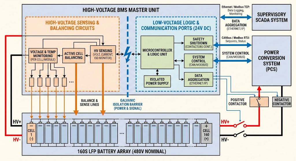
Strategic Overview – The Imperative for 96S-160S BMS in Modern Energy Storage
The landscape of industrial and utility-scale energy storage is undergoing a fundamental voltage transition. Driven by the pursuit of higher efficiency, reduced system losses, and lower balance-of-plant costs, the industry is standardizing on 400V to 800V DC-link platforms for power conversion systems (PCS). This architectural shift creates a direct and non-negotiable requirement for battery management systems (BMS) capable of managing high-series-count (96S to 160S) lithium iron phosphate (LFP) battery strings to directly interface with these elevated DC bus voltages.
The Market Shift: Efficiency at Scale
Operating at 400V+ is no longer an edge-case specification but a core operational driver. For multi-megawatt-hour installations, higher DC voltage minimizes current for a given power level, dramatically reducing I²R losses in cabling and connectors. This translates directly to improved round-trip efficiency and a lower total cost of ownership (TCO). A BMS architected for 96S-160S configurations is therefore not merely a component but a strategic enabler, allowing system integrators to fully capitalize on the economic and performance benefits of modern high-voltage PCS designs.
Defining the Safety-Compliance Gap
The primary technical and commercial risk in deploying these high-string-count arrays lies in BMS selection. A **96S-160S BMS** is not simply a scaled-up version of a low-voltage BMS. It must be designed from the ground up to address the compounded risks of high-potential systems: reinforced isolation, precision high-voltage measurement across all cells, and robust communication integrity in high-electromagnetic-noise environments.
The "Safety-Compliance Gap" emerges when a BMS incapable of meeting these rigorous demands is deployed. This gap is the leading cause of system certification failure, as the BMS is the critical safety monitor for the entire energy storage system (ESS). Standards such as UL 1973 for ESS and IEC 62619 for industrial batteries mandate stringent functional safety and isolation requirements that generic or underspecified BMS units cannot satisfy. Failure to bridge this gap with a purpose-built **96S-160S BMS** jeopardizes project timelines, insurance, and financing.
Core Specifications & Selection Matrix
Selecting a
Battery Management System (BMS) for high-voltage, long-string applications is a critical engineering decision that directly impacts system safety, longevity, and performance. This section decodes the core specifications and provides a framework for evaluating solutions, from entry-level to high-performance systems like the JBD 96S-160S BMS.
Decoding the "S" Count: From 96S to 160S
The "S" count in a BMS specification refers to the number of lithium-ion cells connected in series. This count directly defines the nominal pack voltage and must be matched to the system's DC bus requirements.
* **96S Configuration:** Using standard 3.2V LiFePO₄ cells, a 96S pack yields a nominal voltage of 307.2V. This is a common architecture for high-power industrial equipment and certain energy storage systems (ESS) .
* **160S Configuration:** Extending to 160 series cells pushes the nominal voltage to 512V. This higher voltage tier is increasingly targeted for next-generation commercial ESS and large-scale backup power systems, as it reduces current for the same power level, improving efficiency and reducing conductor costs.
The choice between 96S and 160S is not merely about voltage scaling; it demands a BMS engineered for the heightened challenges of monitoring and protecting extremely long series strings.
Beyond Voltage: The Four Pillars of Selection for Long Strings
When evaluating a
BMS for 96S to 160S applications, voltage capability is just the starting point. A robust selection is built on four foundational pillars:
1. **Measurement Accuracy:** Long strings amplify the impact of cell voltage measurement error. A ±5mV error per cell in a 160S string can lead to a cumulative pack-level error exceeding ±0.8V, causing significant state-of-charge (SOC) miscalculation and unsafe operating conditions. High-precision analog front-end (AFE) circuitry is non-negotiable.
2. **Isolation Integrity:** With system voltages exceeding 500V, reinforced isolation between the high-voltage battery stack and the low-voltage control/logic circuits is paramount for operator safety and system reliability. This includes both functional isolation for communication and basic isolation for voltage sampling channels, rated to withstand transient surges.
3. **Communication Robustness:** Reliable data exchange in electrically noisy high-power environments is critical. While CAN bus is an industry standard, its implementation must include protection against electromagnetic interference (EMI) to ensure deterministic communication for critical protection functions.
4. **Architectural Scalability:** The BMS hardware and software architecture must support the computational load and data management of 160+ cells without performance degradation, allowing for future expansion or configuration changes.
Technical Specification Comparison Matrix
The following matrix contrasts key parameters across typical market segments, highlighting the engineering distinctions that define application suitability.
| Feature |
Entry-Level BMS |
Industry Standard BMS |
JBD High-Performance 96S-160S BMS |
| Max Series Configuration |
Typically <=24S |
Up to 48S - 96S |
96S to 160S |
| Cell Voltage Accuracy |
$\pm$10 mV to $\pm$20 mV |
$\pm$5 mV |
$\pm$2 mV (@ 25°C) |
| Dielectric Isolation (HV to LV) |
1 kV to 2 kV |
> 3 kV |
> 5.2 kV (Enhanced Safety) |
| Primary Comm. Protocol |
UART / RS485 |
CAN 2.0B |
Isolated CAN FD & Ethernet |
| System Topology |
Centralized |
Modular / Distributed |
Master-Slave Distributed Architecture |
| Scalability |
Fixed / Limited |
Moderate |
High; Modular daisy-chain for 96S-160S |
| Target Application |
Small EVs, DIY Projects |
Commercial EVs, Mid-Scale ESS |
Utility-Scale ESS, Industrial Backup, Marine |
As illustrated, a **96S-160S BMS** for mission-critical applications cannot compromise on the pillars of accuracy, isolation, and robust communication. The
JBD solution is engineered to these stringent requirements, providing the precision and safety margin necessary for managing the most demanding high-voltage battery strings.
Technical Deep Dive (Micro) – Engineering a Reliable High-Voltage BMS
For a 96S-160S BMS operating at system voltages exceeding 400V, engineering reliability is a function of precision, isolation, and robust communication. This section details the core technical architectures that prevent state drift and ensure fail-safe operation.
Precision Measurement Architecture: Sub-mV Accuracy at Scale
Achieving and maintaining sub-millivolt (±0.5mV typical) accuracy across 160+ cell voltage channels is the cornerstone of reliable State-of-Charge (SOC) and State-of-Health (SOH) estimation. Drift of just a few millivolts per channel compounds over a large series string, leading to significant pack-level SOC error and accelerated cell imbalance.
Our architecture combats drift through a multi-layered approach:
1. **High-Integrity Signal Path:** Each cell tap connection utilizes a dedicated, low-offset (<1µV) differential amplifier and a 24-bit Sigma-Delta Analog-to-Digital Converter (ADC). This topology rejects common-mode noise from the high-voltage stack.
2. **On-Die Reference & Calibration:** The measurement IC incorporates a precision voltage reference and temperature sensor. An internal calibration cycle, triggered automatically during system idle periods, nulls offset and gain errors caused by temperature drift and aging, ensuring long-term accuracy without manual intervention.
3. **Synchronous Sampling:** All cell voltages across the entire 96S-160S BMS are sampled simultaneously within a microsecond window. This eliminates measurement skew caused by cell current fluctuations during charge/discharge, providing a true "snapshot" of the pack state for accurate calculation.
Figure 2: The JBD High-Performance BMS utilizes a 24-bit ADC and low-offset differential amplifiers to ensure laboratory-grade measurement precision within industrial battery environments.
The Isolation Mandate: System-Level Safety Certification
In high-voltage battery systems, galvanic isolation between the cell stack (high-voltage domain) and the logic/communication interfaces (low-voltage domain) is non-negotiable for safety and functional integrity. Our design implements **reinforced isolation** per international standards to protect users and downstream equipment.
Key specifications include:
* **Working Isolation Voltage:** >1500 V<sub>RMS</sub> to withstand the maximum system voltage (e.g., >700V<sub>DC</sub> for a 160S LFP pack) plus significant safety margin for transients.
* **Creepage & Clearance:** Designed to meet or exceed requirements for **Overvoltage Category III (OVC III)** and **Pollution Degree 2** environments, as defined in IEC 60664-1. For a 1000V<sub>DC</sub> system, this typically requires >8mm creepage/clearance distances across isolation barriers [[Ref: Insulation coordination for equipment within low-voltage supply systems - IEC 60664-1 | International Electrotechnical Commission]].
* **Certification Path:** The isolation subsystem is designed to facilitate end-product certification to critical safety standards such as **UL 1973** for stationary storage and **IEC 62619** for industrial applications, which mandate rigorous dielectric withstand and impulse voltage tests.
This reinforced isolation ensures that a fault in the high-voltage stack cannot create a hazardous voltage on communication lines or the chassis, making the 96S-160S BMS a safe building block for certified systems.
Network Topology for Scale: Reliable Data Collection in Large Arrays
Collecting data from hundreds of measurement points across a large, physically distributed battery array demands a robust, deterministic network. The choice of topology directly impacts reliability, latency, and cost.
| Topology |
Description |
Pros for Large Arrays (96S-160S+) |
Cons for Large Arrays |
| Daisy-Chain (iSPI) |
A single, bidirectional serial loop connecting all BMS slave modules in a chain using differential signaling. |
Simplicity & Cost: Minimal wiring requirements. Deterministic Timing: Fixed latency for full chain scans. High Noise Immunity. |
Single Point of Failure: A physical break in the chain can disrupt downstream communication. Bandwidth Limits: May bottleneck high-speed diagnostics. |
| Star (Isolated CAN) |
Each BMS slave module maintains a dedicated, isolated CAN bus connection to a central master/gateway. |
Maximum Reliability: A failure in one node or cable does not affect the rest of the system. High Bandwidth: Excellent for detailed data streaming. |
Complexity & Cost: Extremely high wire count and complex harnesses. Requires more isolation channels on the master unit. |
| CAN FD (Flexible Data-Rate) |
A multi-drop bus where all modules connect to a common, isolated high-speed bus with variable bit rates. |
Superior Data Throughput: Support for up to 5 Mbps allows for dense data from 160+ cells. Robust Error Handling: Industrial-grade reliability. |
Bus Fault Vulnerability: A short on the main bus trunk can disable the entire network. Termination Sensitivity: Requires precise impedance matching. |
**Implementation Guidance:** For most 96S-160S BMS applications in stationary storage, a **daisy-chain iSPI topology** offers the optimal balance of robustness, cost, and performance. Its deterministic data collection is ideal for tightly synchronized control loops. For highly modular or fault-tolerant architectures where redundancy is paramount, a **star-topology with isolated CAN** may be specified, accepting the increased system complexity.
Integration and Compliance Pathways
A high-voltage 96S-160S BMS is a critical node within a larger energy ecosystem. Its value is fully realized only through seamless integration with power conversion systems (PCS) and adherence to stringent international safety standards. This section outlines the practical pathways for protocol interfacing and the core compliance checklist.
Protocol Interfacing with PCS and Energy Management Systems
Successful integration hinges on robust, deterministic communication between the BMS, the inverter/charger (PCS), and any overarching energy management system (EMS). For high-voltage strings, CAN FD (Controller Area Network Flexible Data-rate) and Modbus RTU are the dominant industrial protocols, each serving distinct roles.
**Best Practices for Reliable Integration:**
1. **Define a Clear Master-Slave Hierarchy:** Typically, the PCS or EMS acts as the communication master, polling the BMS (slave) for critical data packets at a defined interval (e.g., 100ms to 1s). This ensures the PCS receives timely state-of-health information to make operational decisions [[Ref: CAN in Automation (CiA) 454-1 Application Profile for Battery Systems |
can-cia.org]].
2. **Implement Standardized Data Point Mapping:** Avoid proprietary mappings. For CAN FD, utilize established industry profiles like CANopen or specific manufacturer protocol documents. For Modbus RTU, publish a clear register map detailing the function, address, scaling, and units for each parameter (e.g., Cell 1 Voltage, Pack Current, SOC, SOH, Error Codes).
3. **Prioritize Critical Fault Signaling:** Beyond regular data polling, the BMS must be capable of broadcasting high-priority fault messages (e.g., Over-Voltage, Over-Temperature, Insulation Fault) on a dedicated CAN interrupt frame or via a dedicated hardware alarm line. This enables sub-second reaction from the PCS to disconnect or derate.
4. **Validate with Target PCS Brands:** While the underlying protocols are standard, implementation nuances exist. Prior to deployment, confirm:
* **Deye/Sungrow:** Compatibility with their specific CAN message IDs and Modbus register layouts as defined in their technical communication guides.
* **SMA:** Adherence to SMA's Sunny Island Battery Communication protocol, often based on CAN.
* **Generic EMS:** Ensure the BMS's Modbus map aligns with the data point structure expected by platforms like SCADA or home energy managers.
A well-integrated **96S-160S BMS** acts not just as a protector, but as an intelligent data source, enabling advanced energy arbitrage and peak-shaving strategies through the EMS.
The Compliance Checklist for High-Voltage Strings
Compliance is non-negotiable for grid-tied or commercial energy storage systems. It validates the safety, reliability, and performance of the battery system. The following checklist highlights key BMS-related verification points for major standards applicable to high-voltage lithium-ion battery systems.
**Primary Standards & BMS-Critical Items:**
| Standard |
Scope |
Key BMS-Related Compliance Items (96S-160S Systems) |
| UL 1973 |
Batteries for Stationary, Vehicle Auxiliary Power, and Light Electric Rail. |
• Functional Safety: Rigorous verification of protection functions (OVP, UVP, OCP, OTP).
• Safe State Demonstration: Must prove a controlled lockout upon critical fault.
• Dielectric Withstand: Verification of creepage/clearance for BMS circuitry at voltages $>400$ V.
|
| IEC 62619 |
Safety requirements for large-format industrial Lithium cells and batteries. |
• Abnormal Operation Control: BMS must prevent operation outside limits and log all faults.
• Propagation Mitigation: Assessment of BMS response to single-cell thermal events.
• Insulation Monitoring: Mandatory for systems $>60$ V DC; BMS must detect and signal insulation faults.
|
| UN 38.3 |
Recommendations on the Transport of Dangerous Goods (Global Shipping). |
• T7-T8 Overcharge Protection: Specific testing of BMS hardware protection logic.
• Transport SoC: BMS must facilitate and maintain State of Charge (SoC) $\le 30\%$ for air freight compliance.
|
| Regional Grid Codes |
(e.g., IEEE 1547, VDE-AR-N 4105) for Grid Interconnection. |
• SunSpec Modbus Integration: Standardized data reporting (SoC, Power Limits) for grid support.
• Dynamic Response: Verification that BMS and PCS respond to frequency/voltage commands within required timeframes.
|
**Implementation Pathway:**
Engage with a Nationally Recognized Testing Laboratory (NRTL) early in the design phase of your **96S-160S BMS** and battery pack. A "pre-screening" review of the BMS logic, circuit isolation design, and documentation can identify gaps before formal testing, significantly reducing time and cost to certification.
Frequently Asked Questions (FAQ)
This section addresses common technical and strategic questions regarding the design and deployment of high-voltage battery energy storage systems (BESS) utilizing 96S-160S BMS architectures.
Q: We are designing a system around a 480V AC power conversion system (PCS). What is the optimal BMS string count (S) for an LFP system?
**A:** For a 480V AC system, the DC bus voltage on the battery side typically targets a range of ~700-800V to optimize inverter efficiency. Using standard 3.2V nominal Lithium Iron Phosphate (LFP) cells, a 160S (160-series) configuration provides a nominal 512V. After accounting for voltage sag under high load and the inverter's minimum operating voltage window, the optimal range to maximize energy utilization and system efficiency is 140S to 160S. This configuration ensures the battery stack voltage remains within the inverter's high-efficiency band throughout the discharge cycle, directly impacting total energy throughput and return on investment. Proper sizing is a fundamental principle of system design [[Ref: IEEE Guide for the Design and Operation of Battery Energy Storage Systems | IEEE Std 2030.2.1-2019]].
Q: How critical is cell voltage measurement accuracy for the longevity of a 150S+ battery array?
**A:** Measurement accuracy is paramount for system longevity and economic performance. With a typical industry-standard measurement error of ±10mV per cell, the total pack voltage uncertainty in a 150S array balloons to ±1.5V. This uncertainty forces the battery management system to use a conservative, narrower operating voltage window to avoid damaging any cell, effectively wasting over 5% of the system's usable capacity. Implementing a high-precision **96S-160S BMS** with accuracy of ±2mV or better minimizes this voltage uncertainty. This allows the system to safely utilize a wider, more optimal voltage window, maximizing cycle life and protecting the project's ROI by ensuring full access to the purchased energy capacity.
Q: Are JBD's high-string-count BMS systems compatible with inverters like Deye or Victron?
**A:** Yes, full compatibility is achieved through support for standard industrial communication protocols. Victron Energy systems typically utilize the CAN bus (either VE.Can or CAN BMS protocol). Inverters from Deye, Solis, and similar OEMs commonly use RS485 with the Modbus RTU protocol. A capable BMS, such as the JBD SP25S002 series for high-voltage arrays, is designed to support these protocols simultaneously, acting as the central communication gateway between the battery and the inverter. Therefore, compatibility is determined by the protocol implementation, not the brand, ensuring seamless integration into diverse system architectures.
Q: What is the single biggest safety risk when using a BMS designed for 48V systems on a 400V+ array?
**A:** The most significant risk is **Insulation Coordination Failure**. A BMS designed for a 48V (e.g., 16S) system is not rated for the much higher working voltages and creepage/clearance distances required at 400V DC and above. These low-voltage BMS units lack sufficient galvanic isolation between the high-voltage cell measurement circuits and the low-voltage communication/control ports (e.g., CAN, RS485). In a high-voltage array, this deficiency can lead to ground faults, insulation breakdown, and catastrophic failure, posing severe risks of electric shock or fire. Such an IEC 60664-1:2020 mismatch constitutes an immediate and fundamental compliance failure with international safety standards for high-voltage equipment.
Q: Can we expand a system from 100S to 140S after initial deployment?
**A:** This is only feasible with a modular, master-slave BMS architecture. A fixed 100S BMS cannot be physically or logically expanded to monitor additional cells. A scalable system, like JBD's master-slave solutions for **96S-160S BMS** applications, is designed for this purpose. Expansion is achieved by adding pre-configured slave monitoring boards to the existing master controller's communication bus (e.g., CAN or daisy-chain). The master controller seamlessly integrates data from the new slaves, enabling capacity expansion without replacing the core control hardware, thereby protecting your initial investment and simplifying system growth.